terça-feira, 16 de julho de 2013

ASCII or binary???

Let's finally get this answered...

The reality is that there is no right way of doing it. It all depends on the system you'll be using.
If you'll program the software that will be running on your PC, or on another microcontroller and you don't need to keep the format open and accessible to other platforms, then go ahead with a form of binary transfer of data. You will still need to create a header and termination field, and for that you can use ASCII characters, but the data can be serialized and sent down the line like this.
unsigned int variable = 1234;

Serial.print((unsigned char) (variable >> 8) & 0x0F); //shift the higher byte to the right and mask whatever was left behind
Serial.print((unsigned char) variable & 0x0F); //mask the upper byte... and send the other

And this would be the reception code...

unsigned int variable = 0;

variable = Serial.read() << 8; //shift the first byte to the left

variable = variable + Serial.read(); //write the second byte in it's place.


Obviously, bigger data types such as double, float or longs would require more bytes (and sequential shifts of 16 and 24 bits).

The bigger benefit of sending data this way is really to avoid conversion routines that are normally quite costly in terms of processing time.

Now... would there be a way of cutting down the data transfer even further? Well... in some cases, yes. If you've seen any of my code, you'll notice that I pay extra attention to keep the variable size as small as possible. But sometimes, for example floating point variables, will take up four bytes even if you keep a value very small.

So say, for example, that your application needs to transmit the temperature of something and you need to have a floating point. Normally most sensors will only give you a precision of one decimal place, so that's what we'll be looking to transmit.

If you use a floating point, you'll send 4 bytes. But as most temperatures (that you'd use in a hobbyist project at least) will be below 1000 ºC, we can change the floating point value to fit in an integer.

An integer will normally have two bytes meaning that it will go from -32.768 to 32.767 or 0 to 65.535. So this means that if you want a decimal place on your temperatures, you can represent temperatures ranging from -3276,8 to 3276,7 ºC... that's a lot of heat...

So, to do this, one would multiply it's floating point value by 10 (or 100 depending on the number of decimal places you need) and then cast it into an int.
float variable = 123.4567;
int variable_int = 0; 

variable = variable * 10; //one decimal place

variable_int = (int) variable; //this is a cast 

One could then send the variable_int and upon receiving it on the other end, all you'd have to do is to multiply it by 10 and keep it in floating point data type.

This can also be done when sending data in ASCII as it would prevent you from converting floating point ASCII to float format ( with atof() ). But more on that later on.

Hope this cleared the question and because of the limited use of binary data transfer, I'll focus a bit more on the ASCII data transfer... although, remember that most of what is said about protocols can be used in both ways.



sexta-feira, 12 de julho de 2013

Protocols... the message format.

Hello,

As I've been explaining, there are various ways of sending data but the most important way is that both parties (or more) both understand how the communication is done.

One can divide this into semantics and syntax. Semantics, will be the meaning of what is sent... both sides are expecting ASCII or binary. And syntax is the order in which data is sent so that both sides know what they mean.

A good example of this is a call to a function. Let's take for example itoa().

An example call to itoa() would be:

itoa (val, str, 10 );

Obviously by looking at the variables one can understand that val is the value to be converted, str is the string in which the result will be stored and 10 is the numerical base. But imagine that this is what you had in front of you:

itoa (var1, var2, var3);

Without knowing what should go into var1, 2 and 3, it would be impossible to get the function to work properly.

With protocols and communication is the same thing. Both sides need to know that after parameter A, comes parameter B. These "parameters", normally called fields, can either be separated by characters or have fixed length.

Normally, a message will have a Header and a Body (if you know HTML, this will not be a surprise). The header will normally carry information about the message (sender, destination, ID, Type, Code, Checksum) and the body will carry the data.
In the NTP protocol (to get time from the internet), the body will carry the number of seconds since Epoch (1/1/1970).

So, one possible implementation of a message could be:

char MessageStart - A character for synchronizing the communication.
char Type - Type of message. This can be a request or command. A request can be marked by a '?' and a command by '!', a status or reply could be marked by '.'.
char Code - Code of the message. This will define which parameter the system is requesting or issuing a command to.
char * Data - Data to be sent.
char MessageEnd - A character to know the message has ended.

So if I sent <?T> to the Arduino it could mean that I was requesting the current temperature. In this case, since I was just asking, there's no Data to be sent.
The Arduino could then reply with <.T23>.

And this is where the problem starts... should we send it in binary or ASCII?

Stay tuned for the next post... data types. 

quarta-feira, 10 de julho de 2013

Protocols [Part deux]

Hello again...

Let's carry on with the protocols.

As I mentioned before, you can either have an ASCII or binary protocol... or with both.
You see, for simplicity when reading the code, it's nice to have an ASCII character to define the command/status, and for simplicity (in case numbers are being transmitted) sending the data in binary form.

The main advantage of sending data in binary form is space and processing overhead.
For example, say that you have a system where your Arduino sends some information to the computer in this format (in ASCII):

!C30000\n

! signifies the message start
C - signifies the variable that is being sent, lets assume the number of pulses from the electricity counter.
30000 is the number of pulses at the moment.
\n is the end of the message. In C, '\n' is a single character.

This message would take 8 bytes to send in ASCII format. Not only that, you would have to take your pulse count variable, convert it to ASCII (Serial.print does this "automatically") and send it. Your computer, to calculate the actual power used, would then have to take the string with 30000 and convert it to integer format in order to use it in Power calculations and data logging.

This is quite a lot of effort isn't it?

Another possibility would be to mix the encoding of the message like this:

!CBB\n

BB is two bytes in binary format. So what used to take 8 bytes can now take 5.

Not only that... in ASCII you either send data with variable length (which causes a bit more overhead in the processing of data) or you have to stuff it with 0's to the defined length. Say if you wanted to send 15, you would send 00015.

With this mixed format, this is not a problem. Not only that there is no need to convert these bytes from and to ASCII. These can be used "directly".

And by directly I mean

unsigned int variable = 0;

variable = Serial.read() << 8; //shift the first byte to the left

variable = variable + Serial.read(); //write the second byte in it's place.


Although, as I said, this is something that you'd use if your microcontroller project will interface with a program of some sort on the other end. If it's you on a Serial Port or Arduino IDE, then the best option would really be to use an ASCII format.

Next we'll talk about message formats.


terça-feira, 2 de julho de 2013

Protocols... [Part 1]

Hello,

I participate in a couple of electronics forums such as Arduino's and LeafLabs and a common question that pops up every now and then is how to make two systems "talk" to each other. Most of the time, people already have their hardware in place, be it TTL UART, RS232 and variants, Ethernet or Bluetooth, you name it, but there seems to be a consistent problem in getting both systems or machines to actually talk to each other.

What are protocols?

According to Merriam Webster:

"In computer science, a set of rules or procedures for transmitting data between electronic devices, such as computers. In order for computers to exchange information, there must be a preexisting agreement as to how the information will be structured and how each side will send and receive it. Without a protocol, a transmitting computer, for example, could be sending its data in 8-bit packets while the receiving computer might expect the data in 16-bit packets. Protocols are established by international or industry wide organizations. Perhaps the most important computer protocol is OSI (Open Systems Interconnection), a set of guidelines for implementing networking communications between computers. The most important sets of Internet protocols are TCP/IP, HTTP, and FTP."
This is all fine and pretty, but doesn't really tell us much about our problem...

One example of a high level protocol (which is what we really want to achieve) is HTTP. HTTP will tell your browser how to display a given text and images. Same with XML, where data is, normally, well categorized.

But we really don't need to go that far for most Arduino applicaations...
The simplest communication protocol I've "created", is really the one for my encoder simulator on the Maple board. It only works one way (computer to Maple) and there's no error detection or feedback given.

//--------------+SERIAL COMMUNICATION+--------------  
//take care of comms...
  if (SerialUSB.available() > 0)
    switch(SerialUSB.read()) {
      case '0': {
        freq = 100;
        break;
      }
      case '1': {
        freq = 500;
        break;
      }
      case '2': {
        freq = 1000;
        break;
      }  
      case '3': {
        freq = 50;
        break;
      }
      case 'F': {
        dir = 'F';
        break;
      }
      case 'B': {
        dir = 'B';
        break;
      }
      case 'I': {
        enc.Polarity(INVERTED);
        break;
      }
      case 'N': {
        enc.Polarity(NORMAL);
        break;
      }
      case 'R': {
        enc.reset();
        break;
      }
    }//end switch

  }

As you can see from the above code, if I press a number between 0 and 3 I'll change the "speed" of the encoder, with the letters B and F I change the direction of the encoder, etc...

This is as simple as it gets... it works one way, but what if we actually wanted to specify the frequency at which the encoder will run?

For that we'd have to define how to send that data to the Maple... but first...

ASCII or binary data???

ASCII which stands for American Standard Code for Information Interchange is how most communications are sent between machines. HTTP, for example, uses ASCII. This means that when you see this A on this webpage, the binary number sent by Blogger's server was in fact 65. This is then translated to the A you see.
This shouldn't be a stretch to imagine, imagining numbers, however is a bit weirder. This because, the ASCII code for 4 is not 4, but 52. Go over to asciitable.com and have a look. This may be confusing, but if you think of ASCII as a code it gets easier with time. Also, remember that the Arduino IDE sends data in ASCII.
One experiment you can run to understand this is to download the ASCII Table example from the Arduino IDE and run it. There you'll see this.

But what is binary data?

Well, as we see, humans invented ASCII so they could send letters and numbers based on numbers... because, computers and microcomputers work in numbers... or better yet, in binary sequences
. To them everything is a long sequence of 0's and 1's. So we created ASCII to basically give meaning to these bit sequences.

So, you can either send your data in an ASCII format (that you can read as you type it in the Serial port program) or you can use a binary format. Now... how do you use a binary format?

Say for example that you wanted to send the value 48 in binary data, all you had to do was to type "0" on your serial port and the Arduino would receive the value 48. You could then use it directly in calculations in your program. Now, imagine that you wanted to send "48" in ASCII...
You would have to first send a byte with the value "4" and then another byte with the value "8". Your program would then have to convert these two bytes in binary format so you could use it in your Arduino program.

Hope this makes it clear for all of you. Normally, in small projects where there won't be a dedicated PC program to interface with the microcontroller, we tend to use ASCII as it makes it easier for us to interface with the device. But, when there is a dedicated PC program on one end, then sometimes it's a lot better to transmit data in binary format as it avoids conversion functions inside the microcontroller.
Obviously, when you send strings that will be displayed (on an LCD for example), ASCII is the way to go.

Stay tuned for the next part.


terça-feira, 25 de junho de 2013

London's transportation system...

Hello all,

As you probably don't know, I live in London (the UK one) and I must admit it is the city with the best transportation system in the world. Ok, I haven't been in every country or major city of this planet, but I've been to a few and the only system that gets close is the SMRT in Singapore.

The best thing about the London public transportation system, or TfL as is known in the Uk is its Countdown service (click the link for an explanation).
To use this service all you have to do is go to http://countdown.tfl.gov.uk/, search for the bus stop you need and you'll get a prediction of when the next bus will roll by based on the GPS position of the buses.

This is all good and great... and not really a problem if you have one of the many mobile apps or if you keep a computer always on in your place, but for most people having to go online to check the website or go to the app... might be troublesome.

Wouldn't it be better if we could have an LCD board like this:

Bus stop arrival times
in your hallway or next to your front door so you could always see the next bus coming? Obviously, this is too big for that, but if it could be done with a little LCD display it would be great, right?

That's what I thought... and ended up with this: 


My own personal Bus Arrival notification panel. 

One interesting thing about it is that since a couple of months back, the Thames Clipper River Service is also included in countdown as you can see in the video. 

My original idea was to use an LCD shield and use the keys to create a config menu, however I realized (the hard way) that my Ethernet shield is not compatible with the LCD shield (the backlight control pin is use in the SPI communication) and so had to build my own lcd shield for Arduino... and boy, is that weird spacing a headache or what??? 

Next I'll post more details about this... and the library used... so stay tuned. 

sábado, 22 de junho de 2013

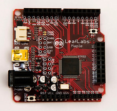
Maple from LeafLabs (an STM32 ARM board in an Arduino footprint).

Hello,

I'm here to talk about the Maple from LeafLabs.com, since some of my latest work has been on this board and processor.

The Maple

As you probably know Arduino launched Arduino Due with an ARM processor a couple of months ago and since then it's been the talk of the interwebs, however, the Maple beat the Due to market by quite a long time.

The big difference is that the chip used in the Maple is from ST whilst the one in the Due is from ATMEL. So the tools to use on them are different and therefor the Arduino IDE can't be used with the Maple.

This being said, the Maple does have its own IDE which is based off of the Arduino's, so it's not like you need to learn a completely new environment to work with it.

Starting with the Maple can be a bit daunting. The amount of peripherals and configuration possibilities is almost endless (in comparison with a normal AVR arduino at least), but there's examples to get you started.
One thing to have in mind is voltages, the Maple works with 3,3V and not all the pins support 5V.

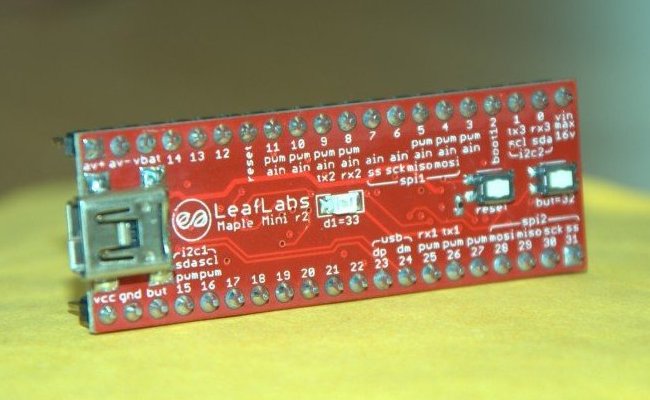
There's also a Maple Mini...

Maple Mini
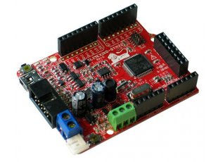
And a pretty good clone from Olimex.

Olimexino-STM32

I personally use the Olimexino (mainly for the RTC crystal and SD card slot), but my code libraries work on all the boards shown here.

The downside of the Maple is that some of the Arduino shields (the latest Ethernet shields, for example) aren't compatible because the Maple doesn't have the AVR ICSP connector through which shields that use SPI are connected. But, don't despair... the pluses of the board make up for this little problem. 

So far I created the RTC support for the Maple with the help of some forum members and also an encoder interface so you can use the Maple's counters as an incremental encoder interface. :) 


quarta-feira, 12 de junho de 2013

How to run your arduino chip without an external crystal...

Hello again...

I am a sucker for clocks... from my Tissot down to the Real Time Counter implementations in microcontrollers I love them all. :)

So, and considering that the standard AVR chips inside the Arduinos have an adapted Timer (2, in case you're wondering) for the Real Time Counter application, I decided to have a go at creating an RTC library for Arduinos. And then you hit a brick wall...

Arduinos have an SMD oscillator, so desoldering, finding and soldering a 32kHz crystal would be out of the question. But... I'm no stranger to AVR chips, so I went ahead and developed the library for an old ATmega16 that I had lying around.

After that was finished I came back to the Arduino and decided to use a standalone "Arduino" chip so I could connect the 32 kHz instead of the 16MHz oscillator normally present in the board.

First, and since this is an old Arduino chip, I had to use a 16MHz crystal and capacitors to be able to communicate to the device. You can see how to hook it up here.

However, Arduinos don't have an internal 8MHz crystal version (sadly), so I had to create my own board...
After playing with the fuse calculator online, and finally realizing which bootloader to use, Google spit out this to me.

So all you need to do, is really to copy the file to your hardware folder (create one if you don't have one), inside the Arduino sketch folder and you're good to go.

Then all you need to do is:

- Download the ArduinoISP sketch to your Arduino.
- Connect it as the drawing above.
- Select one of the newly added boards (that match your bare chip).
- Click on Tools -> Burn Bootloader.

Now, the IDE won't respond for some time, but you should see the LEDs on the board flicker as the bootloader is sent to the chip.

And that's it! Chip prepared for an RTC sketch.

For you to download your sketches you'll need something like this or this or this:


Remember, the RX from the FTDI chip goes to the TX of the Arduino and vice-versa.

And that's it. 
All you need then is to download your program and it'll work, slower, but without many external parts. 

See you next time. :)